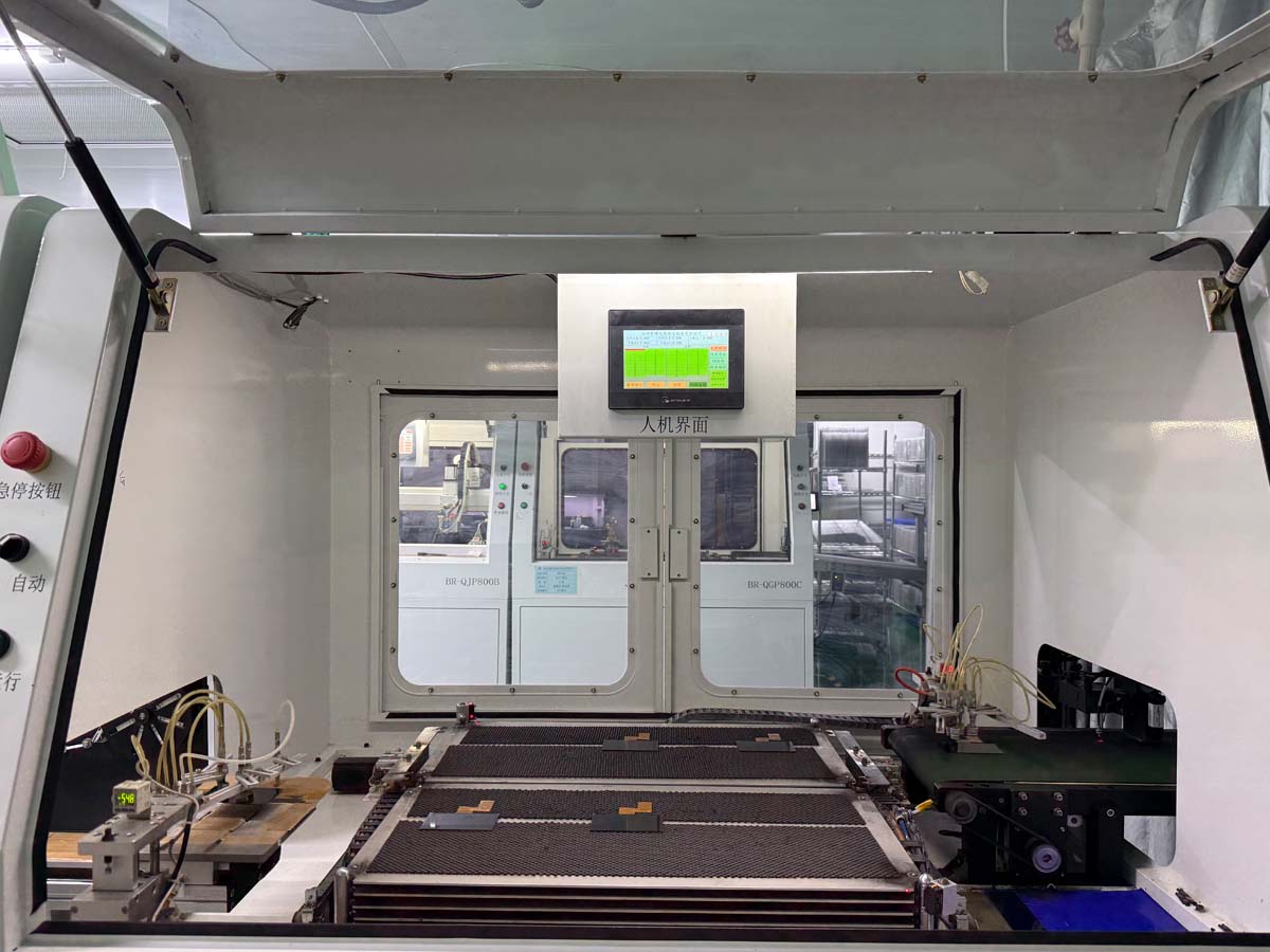
FOG curing is the controlled stabilization stage following flexible-circuit bonding in the TFT LCD production flow. Where required by the selected adhesive and bonding system, controlled thermal or other specified curing conditions help stabilize the bonded interface.
The exact curing method depends on the material system and module design, making temperature, time and handling control important for consistent TFT LCD manufacturing.
Technology Basics
In this production flow, FOG curing refers to the post-bond stabilization or curing stage applied after the flexible circuit has been bonded to the TFT glass.
Depending on the adhesive chemistry and module construction, curing may involve a controlled thermal profile or another specified material process. The objective is to maintain a stable mechanical and electrical connection before final inspection.
Manufacturing Value
The bonded interface must remain stable after precision alignment and compression. Where a post-curing step is specified, consistent process conditions help the joint reach the intended material state before final testing.
Helps the flexible-circuit interface remain mechanically stable after bonding.
A stable bonded interface supports consistent electrical contact through the connection area.
Specified curing conditions help the adhesive system reach its intended performance characteristics.
The stabilized module can then proceed to final functional and visual quality checks.
Process Control
The curing stage should follow the requirements of the bonding material and TFT LCD module design rather than applying one universal temperature or time profile.
The bonded flexible-circuit interface is checked before entering the curing stage.
Required process conditions are selected according to the adhesive material and module specification.
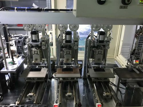
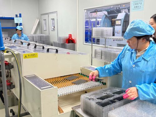
The bonded module undergoes the specified thermal or material curing cycle where post-curing is required.
Time and temperature or other specified curing parameters are controlled throughout the process.
The module is allowed to stabilize after curing before additional handling or testing.
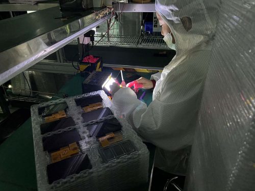
The bonded area is checked before the TFT LCD module proceeds to final inspection.
Process Relationship
Step 4 establishes the flexible-circuit bond. Step 5 stabilizes that interface according to the material system before the display enters final quality inspection.
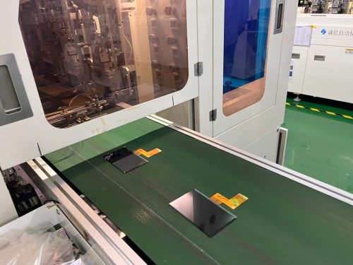
The FPC has been aligned and bonded to the TFT LCD connection area.
The specified curing process prepares the bonded interface for final module inspection.
Review the previous FOB Bonding process.
Quality Assurance
Consistent curing conditions and careful post-process handling help protect the precision bonding work completed in the previous manufacturing stage.
Follow the curing conditions specified for the selected material system.
Maintain appropriate thermal conditions where thermal curing is required.
Control cycle duration according to the bonding material specification.
Check that the flexible circuit remains correctly positioned.
Inspect for visible deformation or abnormal conditions.
Allow appropriate stabilization before final functional testing.
Production Flow
FOG curing follows flexible-circuit bonding and prepares the TFT LCD module for its final visual, electrical and functional quality checks.
Technical FAQ
The curing stage stabilizes the bonded flexible-circuit interface according to the requirements of the selected adhesive or bonding material.
No. Curing conditions vary with the adhesive chemistry, ACF system and TFT LCD module structure.
Where thermal post-curing is required, these parameters influence how the bonding material reaches its intended material state.
The appropriate method depends on the specific adhesive material. The process should always follow the bonding material specification.
The stabilized TFT LCD module proceeds to final inspection for functional, visual and other specified quality checks.
MAXEN supports customized TFT LCD display and touch screen solutions, including display selection, interface customization, touch integration and bonding solutions for industrial applications.



+86-13923461826