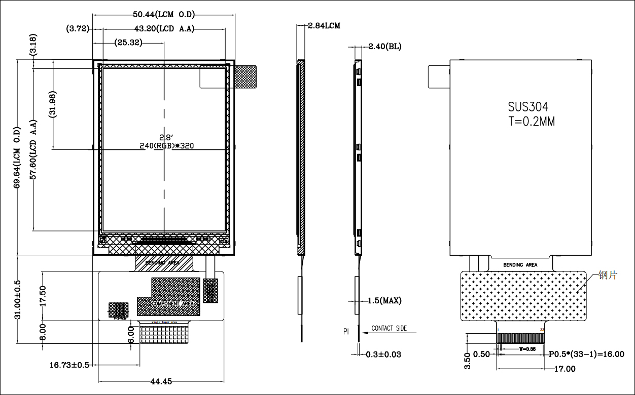


| Pin No. | Symbol | Description | ||
| 1 | LED_A | Anode of LED backlight. | ||
| 2 | LED_K | Cathode of LED backlight. | ||
| 3 | VCI | Power Supply for Analog. | ||
| 4 | GND | Power ground. | ||
| 5 | IM0 | MCU interface mode select | ||
| IM0 | MPU Interface Mode | Data pin | ||
| 0 | 8bit MCU | DB[7:0] | ||
| 1 | 16bit MCU | DB[15:0] | ||
| 6 | RESET | This signal will reset the device and it must be applied to properly initialize the chip. Signal is active low |
||
| 7 | CS | Chip selection pin Low enable. High disable. |
||
| 8 | DC | Display data/command selection pin in parallel interface. DCX='1':display data or parameter. DCX='0':command data. |
||
| 9 | WR | Write enable in MCU parallel interface. | ||
| 10 | RD | Read enable in MCU parallel interface. | ||
| 11~26 | DB0~DB15 | data bus. | ||
| 27 | IOVCC | Power Supply for I/O System. | ||
| 28 | GND | Power ground. | ||
| 29~33 | N/C | Not Connect. | ||
| Parameter | Symbol | Min | Max | Unit |
| Supply voltage for analog | VDD | -0.3 | 4.6 | V |
| Supply voltage for logic | IOVCC | -0.3 | 4.6 | V |
| Supply current (One LED) |
ILED |
30 | mA | |
| Operating temperature |
TOP |
-20 | 70 | ℃ |
| Storage temperature |
TST |
-30 | 80 | ℃ |
| Item | Symbol | Min | Typ · |
Max | Unit |
| Supply Voltage for Analog | VDD | 3.0 | 3.3 | 3.6 | V |
| Supply Voltage for Logic | IOVCC | 1.7 | 3.3 | 3.6 | V |
| Input Voltage |
VIL |
GND | — | 0.3IOVCC | V |
|
VIH |
0.7IOVCC | — | IOVCC | ||
| Input leakage Current |
ILKG |
-1 | — | 1 | μA |
| Item | Symbol | Value | Unit | Remark | ||
| Min. | Typ. | Max. | ||||
| Voltage for LED Backlight |
VF |
5.6 | 6.2 | 6.8 | V |
IL=15mA |
| Current for LED Backlight |
IL |
— | 60 | — | mA | — |
| Power Consumption | P | — | 0.372 | — | W | — |
| LED Life Time | — | 30,000 | 50,000 | — | Hr | Note |
Note: Brightness to be decreased to 50% of the initial value at ambient temperature TA=25℃.