
| Pin No. | Symbol | Description | Pin No. | Symbol | Description |
| 1 | RXO0- | Negative LVDS differential data input(Odd data) | 16 | RXE1+ | Positive LVDS differential data input(Even data) |
| 2 | RXO0+ | Positive LVDS differential data input(Odd data) | 17 | VSS | Ground |
| 3 | RXO1- | Negative LVDS differential data input(Odd data) | 18 | RXE2- | Negative LVDS differential data input(Even data) |
| 4 | RXO1+ | Positive LVDS differential data input(Odd data) | 19 | RXE2+ | Positive LVDS differential data input(Even data) |
| 5 | RXO2- | Negative LVDS differential data input(Odd data) | 20 | RXEC- | Negative LVDS differential data input(Even clock) |
| 6 | RXO2+ | Positive LVDS differential data input(Odd data) | 21 | RXEC+ | Positive LVDS differential data input(Even clock) |
| 7 | VSS | Ground | 22 | RXE3- | Negative LVDS differential data input(Even data) |
| 8 | RXOC- | Negative LVDS differential data input(Odd clock) | 23 | RXE3+ | Positive LVDS differential data input(Even data) |
| 9 | RXOC+ | Positive LVDS differential data input(Odd clock) | 24 | VSS | Ground |
| 10 | RXO3- | Negative LVDS differential data input(Odd data) | 25 | SCL | I2C BUS |
| 11 | RXO3+ | Positive LVDS differential data input(Odd data) | 26 | SDA | I2C BUS |
| 12 | RXE0- | Negative LVDS differential data input(Even data) | 27 | WP | EEPROM write EN |
| 13 | RXE0+ | Positive LVDS differential data input(Even data) | 28 | VCC | Power Supply: +5V |
| 14 | VSS | Ground | 29 | VCC | |
| 15 | RXE1- | Negative LVDS differential data input(Even data) | 30 | VCC |
| Pin No. | Symbol | Description |
| 1 | VCC | Power supply voltage +12V |
| 2 | VCC | Power supply voltage +12V |
| 3 | ON/OFF | Output enable signal |
| 4 | DIM | Dimming signal |
| 5 | GND | Power ground |
| 6 | GND | Power ground |
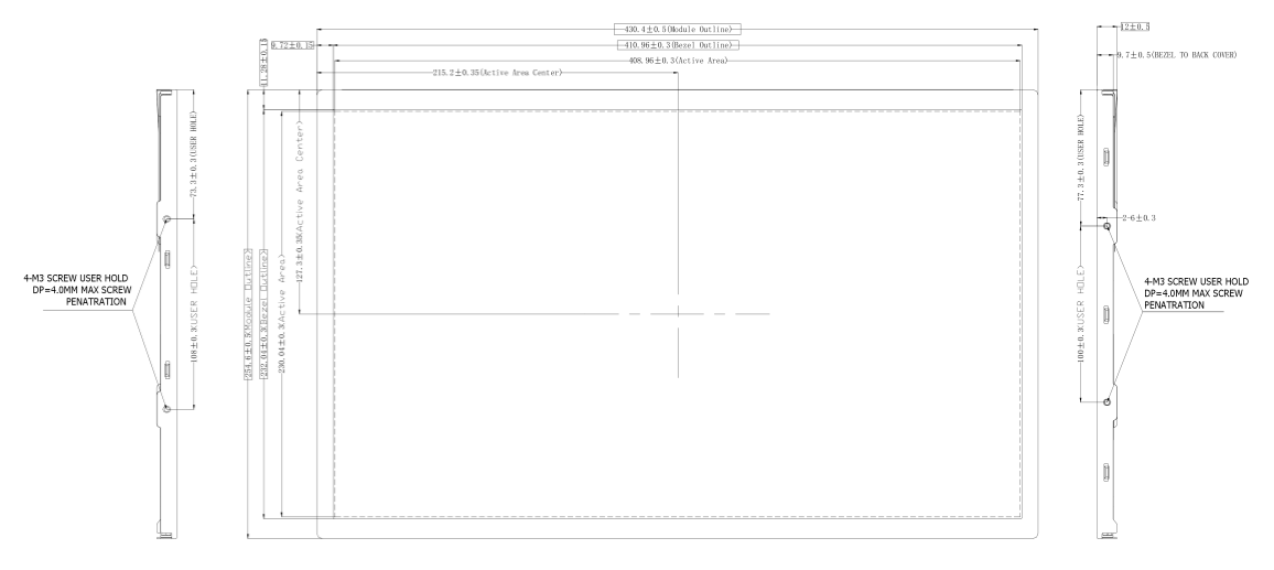
PH2.0-6 (2.0mmX6)
| Parameter | Symbol | Min. | Type. | Max. | Unit | Remarks |
| Back-light Power Supply Voltage |
HVDDOUT |
— | 46 | — | V | Ta=25℃ Note 1&2 |
| Back-light LED Current |
IHVDD |
— | 450 | — | MA | |
| Back-light LED Reverse Voltage |
VR |
— | — | — | V | |
| Power Supply Input Voltage |
VCC |
3.5 | 5 | 5.8 | V |
Note:
1.These range above is maximum value not the actual operating temperature. ActualOperating temperature is no more than 40℃ and temperature refers to the LCM surface temperature;
2.BOE is not responsible for product problems beyond the use conditions.
3.When the ambient temperature is T℃, the surface temperature of Panel can not exceed (T+15)℃.
| Parameter | Symbol | Values | Unit | ||
| Min | Typ | Max | |||
| Power Supply Input Voltage |
VDD |
4 | 5 | 6 | V |
| Power Supply Current |
IDD |
— | 500 | — | mA |
| LED Driver Power Supply Voltage |
HVDD |
10.8 | 12 | 12.6 | V |
| LED Driver Power Supply Current |
IHVDD |
— | TBD | — | mA |
| Positive-going Input Threshold Voltage |
VIT+ |
— | — | +100 | mV |
| Negative-going Input Threshold Voltage |
VIT- |
-100 | — | — | mV |
| Differential input common mode voltage |
Vcom |
— | 1.2 | — | V |
| Parameter | Min. | Typ. | Max. | Unit | ||
| Power supply voltage for Backlight |
VLED |
— | 12 | — | V | |
| Power supply Current for Backlight |
ILED |
— | TBD | — | mA | |
| EN Control Level |
Backlight on |
VENH |
2.5 | — | — | V |
| Backlight off |
VENL |
— | — | 0.8 | V | |
| PWM Cont rol Level |
PWM High Level |
VPML |
2.5 | — | — | V |
PWM Low Level |
VPML |
— | — | 0.8 | V | |
| PWM Control Frequency |
FPWM |
0.12 | — | 1 | KHz | |
| Duty Ratio | — | 5 | — | 100 | % | |