| Pin No. | Symbol | Description |
| 1 | LEDA | LED backlight anode |
| 2~3 | LEDK | LED backlight cathode |
| 4 | GND | Power ground |
| 5 | VCC | Analog power supply |
| 6 | RESET | Reset signal(low active) |
| 7~8 | NC | NC |
| 9 | SDA | Serial data input pin in serial bus system interface |
| 10 | SCK | Pixel clock signal input pin |
| 11 | CS | Chip select |
| 12 | PCLK | Pixel clock signal in RGB interface |
| 13 | DE | Data enable signal in RGB I/F mode |
| 14 | VSYNC | Vertical synchronizing signal input pin |
| 15 | HSYNC | Horizontal synchronizing signal input pin |
| 16~33 | DB0~DB17 | RGB data signal (DB0: BLUE LSB; DB5: BLUE MSB; DB6: GREEN LSB; DB11: GREEN MSB; DB12: RED LSB; DB17: RED MSB) |
| 34 | GND | Power ground |
| 35 | TP_INT | INT pin for CTP |
| 36 | TP_SDA | SDA pin for CTP |
| 37 | TP_SCL | SCL pin for CTP |
| 38 | TP_RESET | Reset pin for CTP |
| 39 | TP_VCl | Power supply for CTP |
| 40 | GND | Power ground |
| Parameter | Symbol | Min | Max | Unit |
| Power Supply voltage 1 | VCl~GND | -0.3 | +4.6 | V |
| Power Supply voltage 2 | IOVCC~GND | -0.3 | +4.6 | V |
| Logic Input Voltage Range | Vin | -0.3 | IOVCC+0.5 | V |
| Logic Output Voltage Range | Vo | -0.3 | IOVCC+0.5 | V |
| Operating temperature | Topr | -20 | +70 | ℃ |
| Storage temperature | Tstg | -30 | +80 | ℃ |
| Parameter | Symbol | Min | Typ | Max | Unit |
| Supply voltage for analog circuit | VCI | 2.5 | 2.8 | 3.6 | V |
| Supply voltage for logic circuit | IOVCC | 2.5 | 2.8 | 3.6 | V |
| Input voltage 'H'level | VIH | 0.7*IOVCC | 一 | IOVCC | V |
| Input voltage 'L'level | VIL | GND | 一 | 0.3*IOVCC | V |
| Output voltage 'H'level | VoH | 0.8*IOVCC | 一 | IOVCC | V |
| Output voltage 'L'level | VoL | GND | 一 | 0.2*IOVCC | V |
| Item | Symbol | Min | Typ | Max | Unit | Condition |
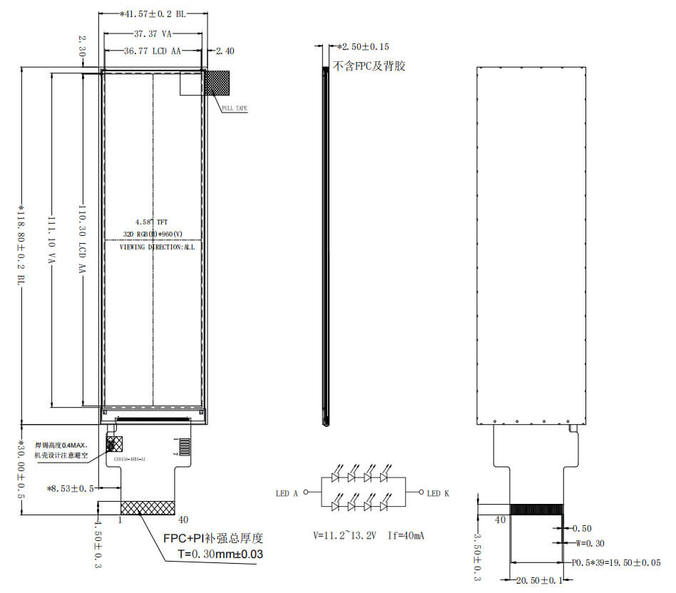
| Forward voltage | Vf | - | 12.8 | - | V | If=40 mA |
| Luminance | LV | - | 300 | - | cd/m² | |
| Number of LED | - | 4X2 | Piece | - | ||
| Connection mode | S/P | 4Serial/2Parallel | - | - | ||