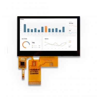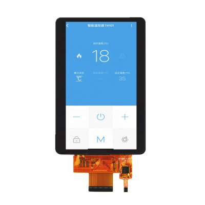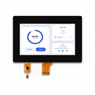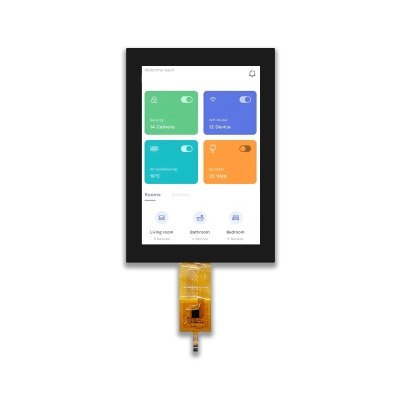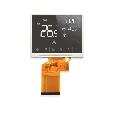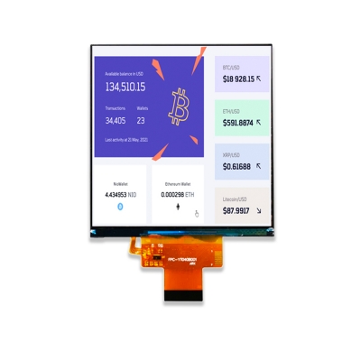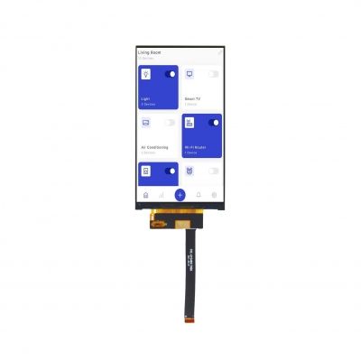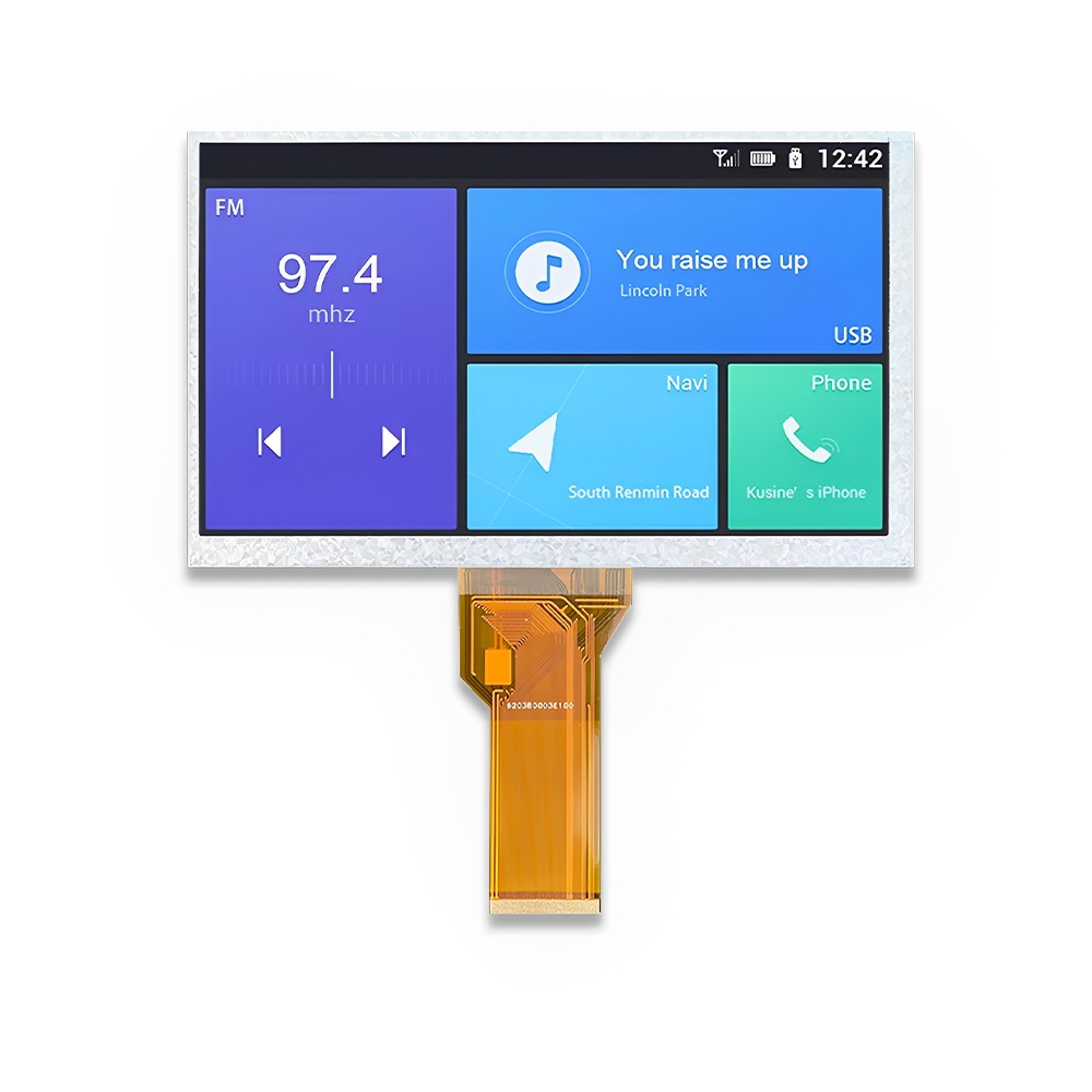


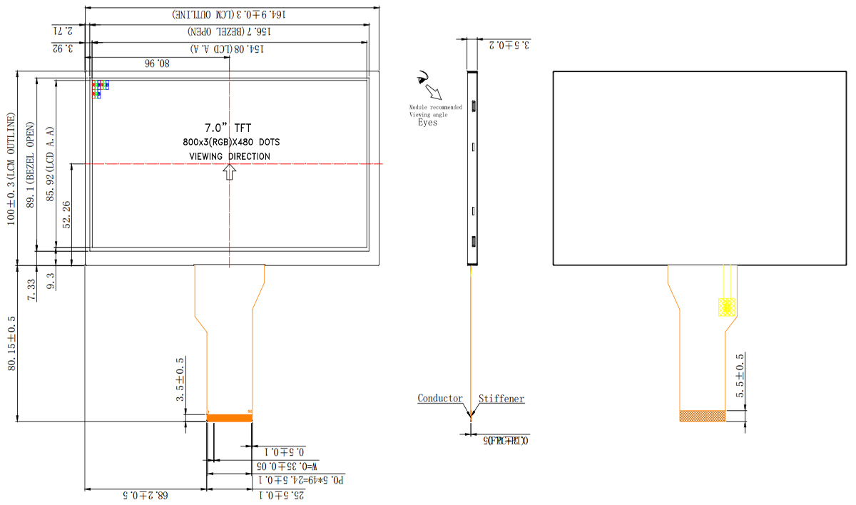
Product Structure
LCD PIN Function (RGB 50 PIN)
|
PIN |
PIN NAME |
DESCRIPTION |
|
1 |
LEDA |
LED backlight (Anode) |
|
2 |
LEDA |
|
|
3 |
LEDK |
LED backlight (Cathode) |
|
4 |
LEDK |
|
|
5 |
GND |
Power ground |
|
6 |
VCOM |
Common Voltage |
|
7 |
DVDD |
Digital Power |
|
8 |
MODE |
DE/SYNC mode select. Normally pull high. |
|
H: DE mode. L: HSD/VSD mode. |
||
|
9 |
DE |
Data Enable signal |
|
10 |
VS |
Vertical sync input. Negative polarity. |
|
11 |
HS |
Horizontal sync input. Negative polarity. |
|
12 |
B7 |
Blue Data Input (MSB). |
|
13 |
B6 |
Blue Data Input |
|
14 |
B5 |
Blue Data Input |
|
15 |
B4 |
Blue Data Input |
|
16 |
B3 |
Blue Data Input |
|
17 |
B2 |
Blue Data Input |
|
18 |
B1 |
Blue Data Input |
|
19 |
B0 |
Blue Data Input (LSB). |
|
20 |
G7 |
Green Data Input (MSB). |
|
21 |
G6 |
Green Data Input |
|
22 |
G5 |
Green Data Input |
|
23 |
G4 |
Green Data Input |
|
24 |
G3 |
Green Data Input |
|
25 |
G2 |
Green Data Input |
|
26 |
G1 |
Green Data Input |
|
27 |
G0 |
Green Data Input (LSB). |
|
28 |
R7 |
Red Data Input (MSB). |
|
29 |
R6 |
Red Data Input |
|
30 |
R5 |
Red Data Input |
|
31 |
R4 |
Red Data Input |
|
32 |
R3 |
Red Data Input |
|
33 |
R2 |
Red Data Input |
|
34 |
R1 |
Red Data Input |
|
35 |
R0 |
Red Data Input (LSB). |
|
36 |
GND |
Power ground |
|
37 |
DCLK |
Clock input |
|
38 |
GND |
Power ground |
|
39 |
L/R |
Left or Right Display Control. |
|
40 |
U/D |
Up / Down Display Control. |
|
41 |
VGH |
Positive Power for TFT. |
|
42 |
VGL |
Negative Power for TFT. |
|
43 |
AVDD |
Analog Power |
|
44 |
RESET |
Global reset pin. Active low to enter reset state. Suggest to connecting with an RC reset circuit for stability. Normally pull high. (R=10KΩ, C=1µF) |
|
45 |
NC. |
Not connect |
|
46 |
VCOM |
Common Voltage |
|
47 |
DITHB |
Dithering function enable control. (Normally pull high) DITHB=“L”, to enable internal dithering function. DITHB=“H”, to disable internal dithering function. |
|
48 |
GND |
Power ground |
|
49 |
NC. |
Not connect |
|
50 |
NC. |
Not connect |
Absolute Maximum Ratings
|
Item |
Symbol |
Min. |
Max. |
Unit |
|
Digital Supply Voltage |
DVDD |
-0.3 |
5 |
V |
|
Analog Supply Voltage |
AVDD |
6.5 |
13.5 |
V |
|
Gate On Voltage |
VGH |
-0.3 |
40 |
V |
|
Gate Off Voltage |
VGL |
-20 |
0.3 |
V |
|
Gate On-Gate Off Voltage |
VGH-VGL |
- |
40 |
V |
|
Operating Temperature |
TOP |
-20 |
70 |
°C |
|
Storage Temperature |
TST |
-30 |
85 |
°C |
|
Storage Humidity |
HD |
20 |
90 |
%RH |
Electrical Characteristics
|
Item |
Symbol |
Min. |
Typ. |
Max. |
Unit |
|
Digital Supply Voltage |
DVDD |
3 |
3.3 |
3.6 |
V |
|
Analog Supply Voltage |
AVDD |
10.2 |
10.4 |
10.6 |
V |
|
Gate On Voltage |
VGH |
15.3 |
16 |
16.7 |
V |
|
Gate Off Voltage |
VGL |
-7.7 |
-7 |
-6.3 |
V |
|
Common Voltage |
VCOM |
3.8 |
4 |
4.2 |
V |
|
Logic Input Voltage |
VIH |
0.7DVDD |
- |
DVDD |
V |
|
VIL |
GND |
- |
0.3DVDD |
V |
Backlight Characteristics
|
Item |
Symbol |
MIN. |
TYP. |
MAX. |
UNIT |
Test Condition |
|
Supply Voltage |
Vf |
8.7 |
9.6 |
10.5 |
V |
If=120mA |
|
Supply Current |
If |
- |
120 |
- |
mA |
- |
|
Luminous Intensity |
- |
230 |
250 |
- |
cd/m2 |
If=120mA |
|
Uniformity for LCM |
- |
80 |
- |
- |
% |
If=120mA |
|
Life Time |
- |
- |
50000 |
- |
Hr |
If=120mA |
|
Backlight Color |
White |
|||||