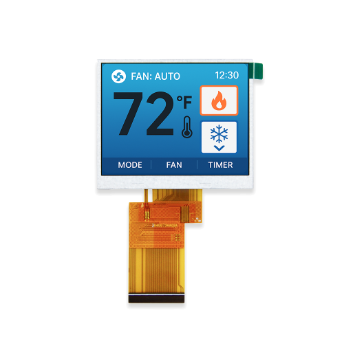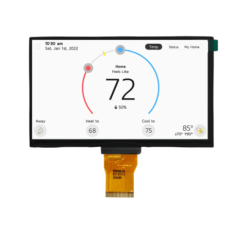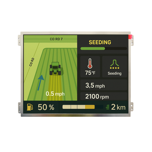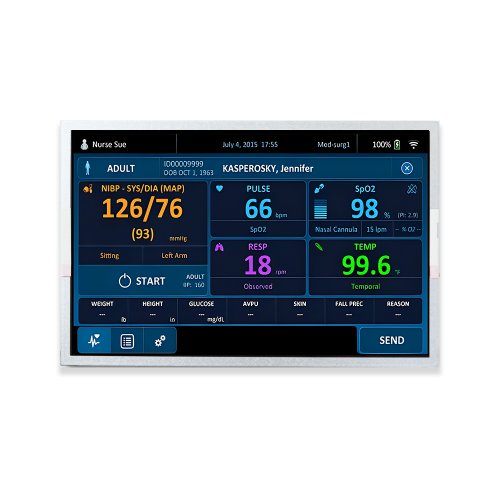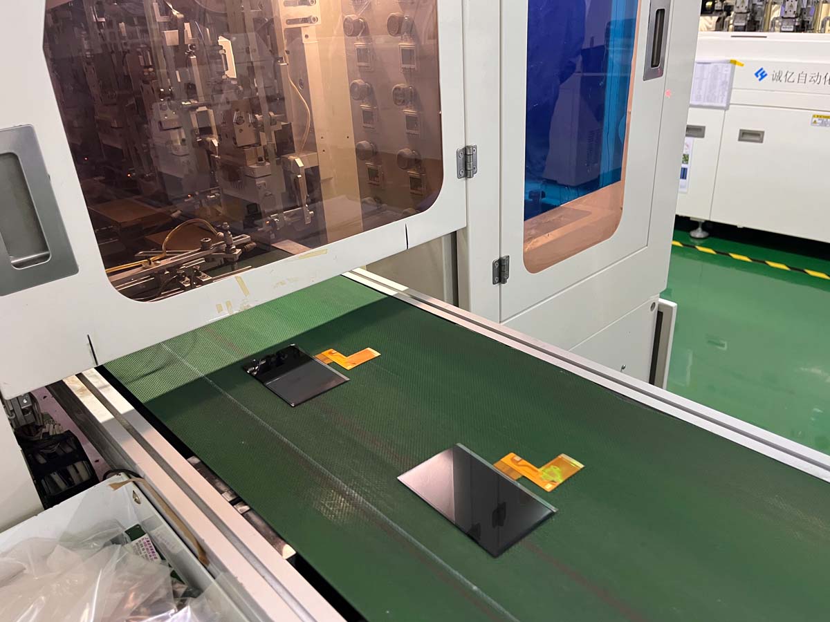
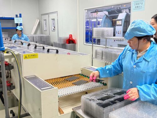
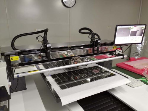
In this TFT LCD production flow, FOB bonding is the precision flexible-circuit bonding stage following ACF lamination. The FPC is aligned with the prepared TFT glass connection area and bonded under controlled process conditions.
Reliable alignment and bonding are essential because these fine-pitch electrical connections carry display signals and power between the TFT LCD panel and the external electronics.
Technology Basics
The FOB / flexible-circuit bonding process aligns the FPC connection pads with the corresponding electrode area prepared during ACF lamination.
Heat and pressure are applied according to the bonding material and module design so that the conductive interface can establish the required electrical connections while maintaining separation between adjacent traces.
Manufacturing Value
Fine-pitch bonding requires accurate positioning and consistent thermal and mechanical control. Alignment errors or contamination can affect signal integrity and the long-term reliability of the display connection.
Helps match flexible-circuit contacts with the corresponding TFT glass electrode pattern.
Consistent bonding supports reliable display signal and power transmission.
Fine-pitch bonding enables dense electrical connections within a compact LCD module structure.
Controlled process conditions help reduce bonding-related electrical and mechanical defects.
Process Control
The flexible-circuit bonding stage combines incoming interface verification, precision alignment, controlled bonding and post-bond inspection.
The prepared TFT glass bonding area is checked before the flexible circuit is positioned.
The flexible circuit and its contact area are checked for orientation, cleanliness and visible damage.
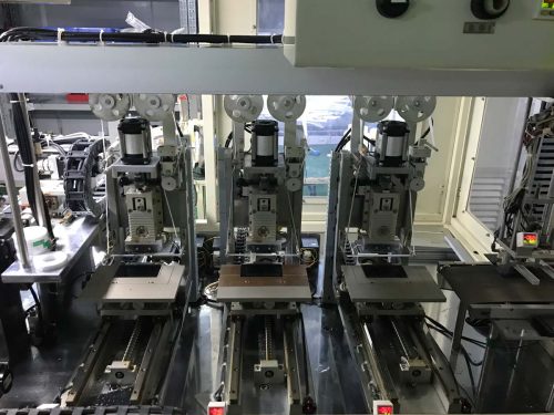
The FPC contacts are aligned with the corresponding TFT glass electrode pattern.
Controlled heat and pressure are applied according to the selected ACF and module bonding requirements.
The bonded interface is allowed to stabilize under controlled conditions before handling.
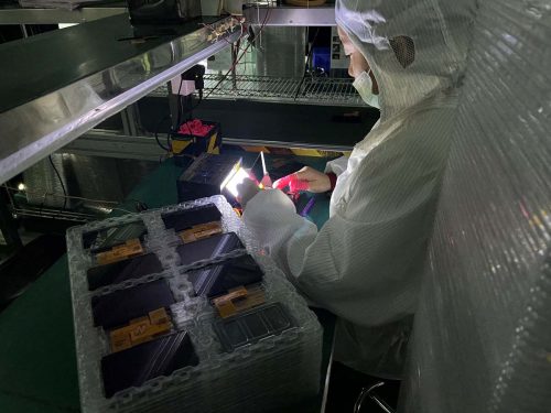
Alignment, surface condition and visible bonding quality are checked before the module proceeds to curing.
Process Relationship
Step 3 prepares the conductive adhesive interface. Step 4 then aligns and bonds the flexible circuit to that prepared TFT connection area.
Anisotropic conductive film creates the bonding interface required for fine-pitch electrical connection.
The flexible circuit is precisely aligned and bonded to establish the required electrical paths.
Review the previous ACF Lamination process.
Quality Assurance
The bond area should be evaluated before the module moves into curing and final electrical inspection.
Confirm that the contact pattern is positioned correctly over the TFT electrodes.
Check for contamination that could interfere with the connection.
Maintain appropriate thermal conditions for the selected bonding material.
Apply consistent pressure across the required bonding area.
Inspect for displacement, wrinkles or other abnormal conditions.
Maintain repeatable process conditions across manufacturing batches.
Production Flow
FOB bonding follows ACF lamination and establishes the flexible-circuit connection before the bonded interface moves into the curing stage.
Technical FAQ
It establishes the electrical connection between the flexible circuit and the prepared TFT LCD connection area.
The contact pads on the flexible circuit must correspond accurately with the TFT electrode pattern to create reliable fine-pitch connections.
ACF provides the adhesive and anisotropic conductive interface used to establish electrical connections while helping isolate adjacent traces.
No. Suitable conditions depend on ACF specification, electrode pitch, FPC design and module construction.
The bonded interface proceeds to the curing or stabilization stage specified for the material system before final inspection.
MAXEN supports customized TFT LCD display and touch screen solutions, including display selection, interface customization, touch integration and bonding solutions for industrial applications.



+86-13923461826