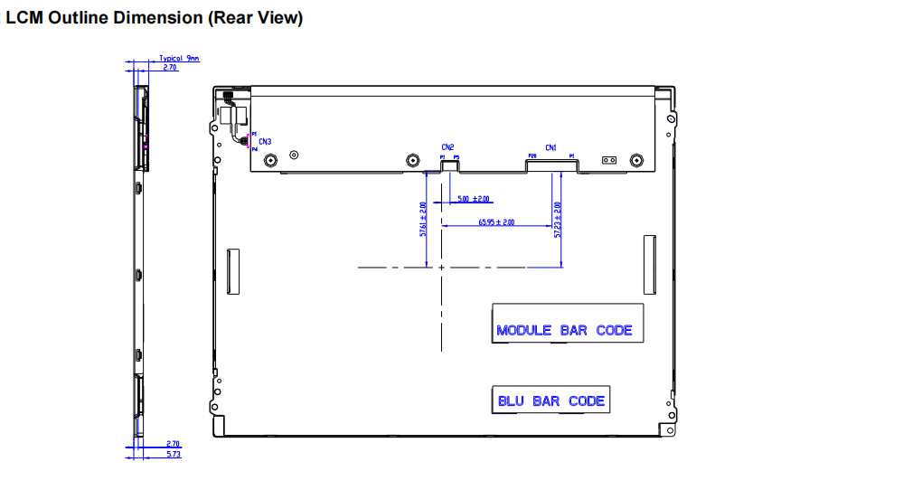
Du bist da: Heim >> Produkt >> TFT LCD Display >> Wide Temperature TFT >> 10,4 Zoll ~ 21,5 Zoll
Produkt
12,1-Zoll-TFT-LCD-Modul mit breitem Temperaturbereich
  • 12,1-Zoll-TFT-LCD-Modul mit breitem Temperaturbereich
  • 12,1-Zoll-TFT-LCD-Modul mit breitem Temperaturbereich
  • 12,1-Zoll-TFT-LCD-Modul mit breitem Temperaturbereich
  • 12,1-Zoll-TFT-LCD-Modul mit breitem Temperaturbereich

12,1-Zoll-TFT-LCD-Modul mit breitem Temperaturbereich


Teilenummer: MX-121SN-01-V403
► Größe: 12,1 Zoll
► Auflösung: 800*600 Pixel
► Anzeigemodus: TN
► Helligkeit: 1200 Nits
► Schnittstelle: LVDS 20 PIN
► Betriebstemperatur: -30°C~85°C
► Touchscreen: Ohne (optional)

    MX-121SN-01-V403 ist ein robustes 12,1-Zoll-TFT-LCD-Modul. Es umfasst ein TFT-LCD-Display, Treiber- und Stromversorgungsschaltungen sowie ein LED-Hintergrundbeleuchtungssystem, die zusammen ein nahtloses Seherlebnis bieten. Das Modul unterstützt SVGA mit einer Auflösung von 800 (H) x 600 (V) und kann 16,7 Mio. (8 Bit) oder 262.000 Farben (6 Bit) anzeigen, wodurch es vielseitig für verschiedene visuelle Anforderungen geeignet ist. Alle Eingangssignale werden nahtlos über die LVDS-Schnittstelle weitergeleitet. Das für optimale Anzeige konzipierte 12,1-Zoll-LCD-Display bietet einen weiten Betrachtungswinkel von 65/75/80/80 Grad und eine hohe Helligkeit von 1200 Nits, was es ideal für industrielle Anwendungen macht. Das 12,1-Zoll-TFT-LCD arbeitet in einem weiten Temperaturbereich von -30 bis 85 °C und ist für eine lange Lebensdauer mit einer langlebigen LED-Hintergrundbeleuchtung ausgestattet.

    Product Structure


    TFT-LCD Interface Signal Description

    Pin No.

    Symbol

    Description

    Remark

    1

    VDD

    Power Supply, 3.3V (typical)


    2

    VDD

    Power Supply, 3.3V (typical)


    3

    GND

    Ground


    4

    SEL68

    6/ 8bits LVDS data input selection [H: 8bits L/NC: 6bit]

    Note1.2

    5

    RIN0-

    LVDS receiver signal channel 0

    Note1

    6

    RIN0+

    LVDS Differential Data Input (R0,R1,R2,R3,R4,R5,G0)

    7

    GND

    Ground


    8

    RIN1-

    LVDS receiver signal channel 1

    Note1

    9

    RIN1+

    LVDS Differential Data Input (G1,G2,G3,G4,G5,B0,B1)

    10

    GND

    Ground


    11

    RIN2-

    LVDS receiver signal channel 2

    Note1

    12

    RIN2+

    LVDS Differential Data Input (B2,B3,B4,B5,HS,VS,DE)

    13

    GND

    Ground


    14

    CLKIN-

    LVDS receiver signal clock

    Note1

    15

    CLKIN+

    16

    GND

    Ground


    17

    RIN3-

    LVDS receiver signal channel 3


    18

    RIN3+

    LVDS Differential Data Input (R6,R7,G6,G7,B6,B7,RSV)
    pin17=VDD & pin18=GND for 6bit LVDS Input

    Note1

    19

    REVERSE

    Reverse Scan Function [H:Enable; L/NC:Disable]

    Note1.2.3

    20

    NC/GND

    Reserved for AUO internal test. Please treat it as NC.

    Note2

    Note 1: Input Signals shall be in low status when VDD is off.
    Note 2: High stands for “3.3V”, Low stands for “0V”, NC stands for “No Connection”.
    Note 3: There is a pull-low resistor 10Kohm on PCB, so please input "3.3V" directly for H status and "0V" directly for L status.
     
    Absolute Ratings of TFT LCD Module

    Item

    Symbol

    Min.

    Max.

    Unit

    Logic/LCD Drive Voltage

    VDD

    -0.3

    3.8

    [Volt]

    Control Signals

    SEL68, REVERSE

    -0.3

    VDD

    [Volt]

    LVDS Signals

    CLKIN-/+, RIN0~3-/+

    -0.3

    VDD

    [Volt]

    LED Input Voltage

    VCC

    -0.3

    13

    [Volt]

    LED Control Signals

    EN, PWM

    -0.3

    6

    [Volt]


    Absolute Ratings of Environment

    Item

    Symbol

    Min

    Max

    Unit

    Operating Temperature

    TOP

    -30

    85

    []

    Operation Humidity

    HOP

    5

    95

    [%RH]

    Storage Temperature

    TST

    -30

    85

    []

    Storage Humidity

    HST

    5

    95

    [%RH]

    Note: Maximum Wet-Bulb should be 39℃ and no condensation.

    LCD Electrical Specification

    Symbol

    Parameter

    Min.

    Typ.

    Max.

    Units

    Remark

    VDD

    Logic/LCD Input Voltage

    3

    3.3

    3.6

    [Volt]


    IVDD

    LCD Input Current

    -

    0.2

    0.24

    [A]

    VDD=3.3V at 60 HZ, all Black Pattern

    PVDD

    LCD Power consumption

    -

    0.66

    0.79

    [Watt]

    VDD=3.3V at 60 HZ, all Black Pattern

    Irush LCD

    LCD Inrush Current

    -

    -

    1.5

    [A]

    VDD=3.3V at 60 HZ, all Black PatternNote 1 VDD rising time470us

    VDDrp

    Allowable Logic/LCD Drive Ripple Voltage

    -

    -

    100

    [mV]
    p-p

    VDD=3.3V at 60 HZ, all Black Pattern

    VIH

    Control Signals Voltage

    High Level

    0.7*VDD

    -

    VDD

    [Volt]

    SEL68 and REVERSE

    VIL

    Low Level

    0

    -

    0.3*VDD

    [Volt]

    SEL68 and REVERSE


    Backlight Unit
    Following characteristics are measured under stable condition at 25℃. (Room Temperature)

    Symbol

    Parameter

    Min.

    Typ.

    Max.

    Unit

    Remark

    VCC

    Input Voltage

    10.8

    12

    12.6

    [Volt]


    IVCC

    Input Current

    -

    0.33

    0.4

    [A]

    VCC=12V & 100% PWM Duty

    PVCC

    Power Consumption

    -

    3.96

    4.8

    [Watt]

    VCC=12V & 100% PWM Duty

    VEN

    EN Control Level

    BL On

    3

    -

    5.5

    [Volt]


    BL Off

    0

    -

    0.5

    [Volt]


    FPWM

    Dimming Frequency

    200

    -

    20K

    [Hz]


    DPWM

    Dimming Duty Cycle

    5

    -

    100

    %


    VPWM

    Dimming Control Level

    High Level

    3

    -

    5.5

    [Volt]


    Low Level

    0

    -

    0.5

    [Volt]

    IF

    LED Forward Current

    -

    45


    [mA]

    Ta=25

    VF

    LED Forward Voltage

    -

    3.2

    3.6

    [Volt]

    IF=45mA,Ta=25

    PLED

    LED Power Consumption

    -

    3.02

    3.4

    [Watt]


    LED life time


    50,000

    -

    -

    Hrs

    IF=45mA,Ta=25

    Note 1: Ta means ambient temperature of TFT-LCD module.
    Note 2: VCC, IVCC, PVCC are defined for LED backlight. (100% duty of PWM dimming)
    Note 3: IF, VF are defined for one piece LED. There are three LED channels in back light unit.
                3 strings, 7 LEDs for each string, total 21 LEDs.
    Note 4: If MX-121SN-01-V403 module is driven by high current or at high ambient temperature & humidity condition. The operating life will be reduced.
    Note 5: Operating life means brightness goes down to 50% initial brightness. Minimum operating life time is estimated data.

相关产品

MAXEN Electronics

+86-(0769) 8777 0259

+86-139 2346 1826

melody.xia@maxen-lcddisplay.com

40A, Fl.4, No.2 Building, Cosmo Technopark, Fenggang Town, Dongguan 523697, CHINA
Produkt
TFT LCD Display
Touchscreen
Optical Bonding
GESELLSCHAFT
Über uns
Kontakt
News
Videos
Weitere Links
LinkedIn
©2023 Maxen Electronics Limited Alle Rechte Vorbehalten